

TCB-2244A
- 1/2“ Sony CMOS Sensor
- 44X Optical Zoom, 16X Digital Zoom
- Max 60FPS @ 1920 x 1080
- H.265 / H.264 / MJPEG
- Autofocus
- True WDR
- SRT (Secure Reliable Transport)
- RTSP/RTMP/MPEG-TS
- ONVIF, PSIA Compliant
Specifications
Basic Specifications | |
Image Sensor | 1/2 Sony CMOS Sensor |
Minimum Illumination | Color : 0.07 Lux at 1/30sec, 50IRE BW : 0 .0025Lux at 1/30sec, 50IRE |
Analog Gain / Digital Max Gain | 1 to 30 |
Shutter Speed | 1/1 to 1/100000 |
Maximum Aperture Ratio | F1.4 ~ F5.0 |
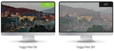
Defog | YES |
Noise Reduction | 2D, 3D |
Gamma | 0, 1, 2, Auto(Normal), Auto(Clear), Auto(Bright), Auto(Fine) |
Wide Dynamic Range | Level 1 to Level 7 |
White Balance | Auto Tracing White, Auto White, Manual |
AE (Auto Exposure Mode) | Auto, Flat, Spot, Center |
Lens (wide to tele) | 44x optical zoom ; f= 6.3mm to 278mm, F1.4 to F5.0 |
Digital Zoom | 16x |
Angle of View | Horizontal : 61.6°(wide) ~ °1.9(tele) / Vertical : 36.0°(wide) ~ °1.1(tele) / Diagonal : 69.5°(wide) ~ °2.2(tele) |
Minimum Focus Length | 1 m to 10 m |
Video |
|
Compression | H.265/H.264/MJPEG |
Frame rate | Max 60fps @ 1920x1080 |
Bitrate | Primary : 32Kbps ~ 16Mbps, Secondary x3 : 32Kbps ~ 4Mbps |
Resolution | 352x240 ~ 1920x1080 |
Streaming | Primary : H.265/H.264, Secondary x 3 : H.265/H.264/MJPEG |
Burn-in OSD | Multi-lingual |
Audio |
|
Compression | G.711 / AAC |
Sampling rate | G.711 : 8 KHz, AAC : 32 kHz / 44.1 kHz / 48 kHz |
Bitrate | G.711 : 64Kbps, AAC: 64Kbps/128Kbps |
Streaming | G.711 : Full-duplex, AAC : Full-duplex |
Input/Output | 1 x Line-In (mono), 1 x Line-Out (mono) - IN / OUT Connector : 0.4mm PITCH CONNECTOR FOR 30pin MICRO COAXIAL CABLE (KEL) |
Network |
|
Protocol | IPv4/v6, TCP, UDP, IGMP(Multicast), ICMP, DHCP, HTTP, HTTP, FTP, SNMP, SMTP, UPnP, WS-Discovery, Zero Configuration, NTP, SRT, MPEG-TS, RTP, RTSP, RTMP, DDNS |
Security | Password protection, IP address filtering, HTTPS encryption, SRT |
API | Truen protocol/SDK, ONVIF, PSIA |
Interface | Ethernet 10/100/1000base-T / Connector : 1.25mm Conn - Connector : 1.25mm PITCH wire to board CONNECTOR (8pin of 12pin) |
Event and Alarm |
|
Event Source | Motion, Sensor input, Client disconnection, Intrusion, Line crossing, Tampering, Face detection, Sound detection, User defined event |
Event actions | Notification(E-mail), FTP, PTZ preset, Alarm control, Recording |
General |
|
Power Supply & Power Consumption | Min DC12V/2A & DC12V: Max 13.6 W |
Operating Temperature | -10°C ~ 50°C ( 14°F ~ 122°F ) |
Operating Humidity | 20% ~ 80% RH |
Edge Storage | SD/SDHC/SDXC slot (Max 256GB) / Connector : Micro-Coaxial |
Dimensions (W x H x D) | 73.3mm X 77.24mm X 173.65mm |
Weight | 724g |


<Front>
| <Top>
| <Bottom>
|
<Rear>
| <Right side>
| <Left side>
|
R0M-J4 | |||||||
Pin No. | Signal | Dir | Description | Pin No. | Signal | Dir | Description |
1 | EXT_RTX+ | I/O | RS-485 + | 16 | 5V | PWR | DC 5V Output (Max 100mA) |
2 | EXT_RTX- | I/O | RS-485 - | 17 | Reserved | I/O | Reserved |
3 | AC_IN_L | I | Audio Line input | 18 | Reserved | I/O | Reserved |
4 | AC_OUT_L | O | Audio Line output | 19 | GND | PWR | Ground |
5 | IP_RESET | I | Factory reset Input(Active Low) | 20 | Reserved GPIO0 | I/O | GPO(For Alarm Output, 3.3V Signal output) |
6 | DAC_CVBS | O | CVBS output | 21 | Reserved GPIO1 | I/O | GPI(For Sensor Input, 3.3V Signal input) |
7 | Reserved | O | Reserved | 22 | 3.3V | PWR | DC 3.3V Output (Max 100mA) |
8 | Reserved | O | Reserved | 23 | 3.3V | PWR | DC 3.3V Output (Max 100mA) |
9 | Reserved | O | Reserved | 24 | SDIO0_DETECT | I | SDIO 0 card detection signal, active low |
10 | Reserved | I | Reserved | 25 | SDIO0_CLK | O | SDIO 0 output working clock for the card |
11 | INTER_Tx1 | O | Connect to INTER_Rx2 | 26 | SDIO0_CMD | I/O | SDIO 0 command |
12 | INTER_Rx1 | I | Connect to INTER_Tx2 | 27 | SDIO0_DATA0 | I/O | SDIO 0 data 0 |
13 | INTER_Tx2 | O | Connect to INTER_Rx1 | 28 | SDIO0_DATA1 | I/O | SDIO 0 data 1 |
14 | INTER_Rx2 | I | Connect to INTER_Tx1 | 29 | SDIO0_DATA2 | I/O | SDIO 0 data 2 |
15 | 5V | PWR | DC 5V Output (Max 100mA) | 30 | SDIO0_DATA3 | I/O | SDIO 0 data 3 |
R0M-J1 | |||
Pin No. | Signal | Dir | Description |
1 | NETWORK_D- | IO | Ethernet Negative Data 4 |
2 | NETWORK_D+ | IO | Ethernet Positive Data 4 |
3 | NETWORK_C- | IO | Ethernet Negative Data 3 |
4 | NETWORK_C+ | IO | Ethernet Positive Data 3 |
5 | NETWORK_B- | IO | Ethernet Negative Data 2 |
6 | NETWORK_B+ | IO | Ethernet Positive Data 2 |
7 | NETWORK_A- | IO | Ethernet Negative Data 1 |
8 | NETWORK_A+ | IO | Ethernet Positive Data 1 |
9 | VIN | PWR | Supply Voltage DC12V |
10 | VIN | PWR | Supply Voltage DC12V |
11 | GND | PWR | Ground |
12 | GND | PWR | Ground |


