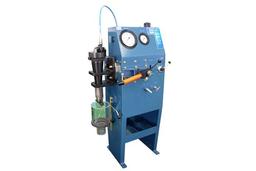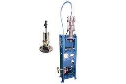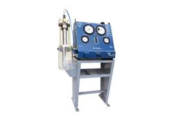


Manufacturer of oil pressure machinery in vessel engine, high pressure pump unit, fule valve test device and more
SPECIFICATION
■ Introduction
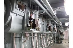
Hydraulic top bracings installed between the engine and the ship's hull to detune the natural frequencies likely to occur during normal operation of the engine.
The hydraulic top bracing cylinder are flexible for movements caused by thermal expansion and varieties of loading conditions of the ship.
The standard installation features two, four or six top bracing cylinders, depending on engine size and cylinder number. The top bracing cylinders are signed with a diameter of Ø200mm, and are delivered with a 41 bar relief valve for engines with bore≥50 to bare <60, and a 64 bar relief valve for engines with bore≥60.
■ Technical Description
The composition of hydraulic top bracing system is as follows;
1. One (two or three) pair(s) of hydraulic top bracing units, depending on the engine type, each consisting of:
a. an oil accumulator.
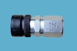
b. a valve block unit with a check valve, two relief valve, a solenoid valve, an oil pressure gauge, a pressure transmitter and two minimess coupling;
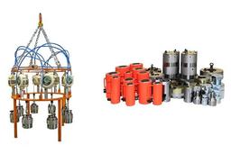
c. a top bracing cylinder unit including mounting flanges and lifting tools(not shown);
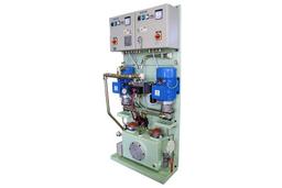
2.. A control panel with a multi function turn switch, a programmable threshold switch, two indication lamps and a test switch for the lamps.
3. A mounting tool used for correct positioning of top bracing flanges.
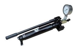
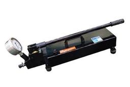
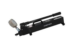
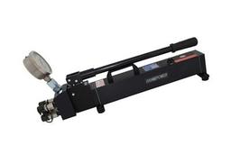
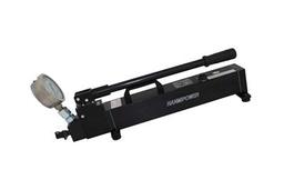
4. A hydraulic hand pump with a 10㎛ pressure filter.
5. A tool box with a set of lifting tools, a filling hose, a bleeding hose, a ball valve, an eyebolt and two tommy bars. Detailed part list are shown in appendix B.
■. Functioning
The hydraulic top bracing consists of a single-acting, self-adjusting unit.
In practice, the oil pressure will increase rapidly when the engine starts to vibrate. The forces are transferred through the top bracing cylinders, which will act as rigid connections and thereby detune the natural frequencies.
An oil pressure gauge and a pressure transmitter are placed in the pipe branch connected to the accumulator to monitor the pressure of the pre-charged hydraulic oil. The measuring range of the transmitter is 0-10 bar and the AMS should give an alarm when the pressure of pre-charged hydraulic oil becomes lower than 6.3 bar.
A solenoid valve is placed in the pipe branch parallel to the branch containing the pressure relief valve.
By means of the solenoid valve, the pertaining pipe branch can be opened or blanked-off.
When the solenoid valve is open, the workspace is directly connected to the accumulator.
This enables a relief down to the pressure of the accumulator and the sealing arrangements are relived.
Practically, the solenoid valve is open when the engine is at standstill and closed when the engine is running. The solenoid valve is controlled by a programmable threshold switch which is connected to the ±10 voltage RPM signal.
