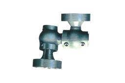


Joint manufacturer, Rotary, Swivel, Ball joint, Syphon hose and more

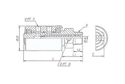
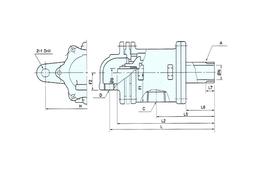
| C | F1 | G | H | I | J | L | L4 | L5 | L6 | N | O | P | Q | R | S | T | U | Net Wt.kg | |
| 25A | PT1 | 52 | 16 | 65 | 14 | 85 | 180 | 144 | 113 | 43 | 23 | 35 | 60 | 80 | 14 | 9 | 4 | Ø11 | |
| 32/40A | PT11/2 | 61 | 15 | 70 | 19 | 110 | 216 | 176 | 129 | 49 | 34 | 50 | 75 | 96 | 16 | 9 | 4 | Ø11 | |
| 50A | PT2 | 73 | 16 | 92 | 23 | 130 | 248 | 204 | 156 | 63 | 48 | 65 | 95 | 120 | 19 | 10 | 4 | Ø11 | |
| 65A | PT21/2 | 84 | 18 | 110 | 23 | 148 | 263 | 210 | 166 | 60 | 60 | 80 | 110 | 136 | 20 | 12 | 4 | Ø11 | |
| 80A | PT3 | 106 | 24 | 125 | 25 | Ø184 | 318 | 260 | 196 | 70 | 70 | 90 | 125 | 154 | 20 | 12 | 6 | Ø14 | 27.5 |

• SHAFT
Shaft rotates by attaching to rotation body including Roller, Drum. For the method of attachment, there are two kinds of [screw type] and [FLANGE type]. As taper screw for pipe of KS, as for direction, from the direction of Roller or Drum rotation to attach Rotary Joint, it's [left screw if clockwise] [right screw if counter-clockwise] In case of Flange, there's no relation with rotation direction of Shaft. In addition, in the middle of Shaft, there's sliding part of spherical surface.
• HEAD
It's the connect part of supply and discharge of fluid, and INNER PIPE is attached to compound. For screw of interior pipe, usually (PE)Look Nut is concluded only with parallel KS PIPE threads. And, in case of Flange Type, interior pipe is done only with right screw and Look Nut is used as parallel KS PIPE threads.
• BODY
In the top middle of Body, there's a hole to install Stopper so prevents rotation of body for the initial rotation. And prevents damage of Flexible Hose.
| MAXIMUM PRESSURE | 15Kgf / ㎠G | |
| MAXIMUM TEMPERATURE | 300℃ | |
| MAXIMUM ROTATION NUMBER | 10A-25A 300rpm | 32A-80A 150rpm |
| FLUID | steam, heat water, heat medium, cooling water, lil, air | |


