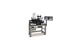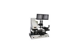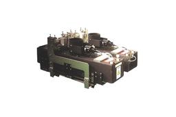


UV exposure, UV curling machine, Laminator, UV lamp, UV LED lamp
Summary
Electronic ballast includes voltage source, electromagnetic half-bridge converter, lamp unit, control circuit, and gate driver. The voltage source supplies a power source, and the electromagnetic half-bridge converter supplies an alternately changing current by using a resonance current flowing through the lamp unit and turning on/off the power switch. At this time, the switching frequency needs to be changed to control the power consumed by the lamp, and performing such a role is the very gate driver and control circuit. The gate driver turns on/off the power switch alternately by turning off the power switch turned off by signals of the control circuit transmitted through the transformer and turning on the opposite power switch using the resonance current flowing into the lamp. Thus, if the cycle of signals coming from the control circuit varies, so does the switching frequency. The electronic ballast from the present invention allows for power control without using the control IC for high-priced electronic ballast.
This system consists of: the lamp unit composed of the resonant circuit and the lamp; voltage source that supplies power to the lamp unit and control circuit; electromagnetic half-bridge converter, including the transformer, that supplies an alternately changing current by using a resonance current flowing through the lamp unit and turning on/off the power switch; control circuit giving the signal for switch turn-off to the gate driver through the transformer so that the switching frequency can vary to control the power of the lamp; and the gate driver that turns off the power switch according to the switch turn-off signal received through the transformer from the control circuit and turns on the power switch alternately after receiving the resonance current of the lamp unit.
Features
① No change in intensity (less than 4kW) -> spheroidization
② Power output and intensity are precisely controlled in linear proportion.
③ Substantially unaffected by input transmission voltage in the CP mode
④ The lamp is initially lit in the LC mode, and 100% lit.
⑤ Quick to stabilize the lamp (available power will be just applied): within 30 seconds
⑥ UV efficiency (power efficiency) is high among the same lamps with the same power and IR heat generation rate is reduced.
⑦ In the CI mode, the intensity can be kept at the setting value regardless of power (transmission voltage and tube voltage are reduced).
⑧ Easy operation and compact size
⑨ Little transformer noise during normal operation (there is a noise during the initial lighting)
⑩ Capable of displaying the warning signal because lamp replacement time is given in the form of a signal)
⑪ The range of output conversion is available to be controlled up to nearly 10 to 100%.
⑫ Unaffected by the lamp cooling amount because automatic power is maintained (easy to control overcooling and overheating: detecting the ideal V/A value based on the cooling amount
⑬ Finding 100% power factor conditions, and little heat generation inside and outside the electronic ballast box.
