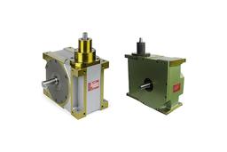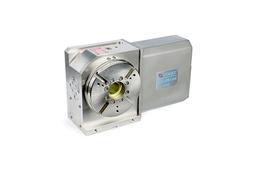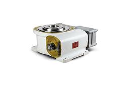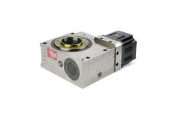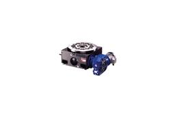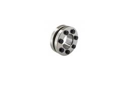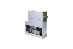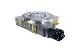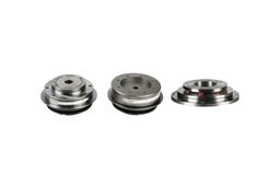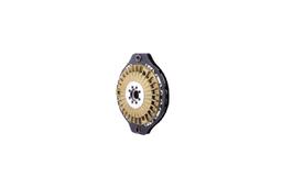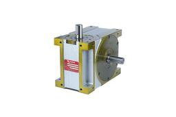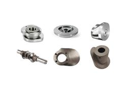
Index drive manufacturer, Shaft, Flange, Table type
Overview & features
Roller Gear Index Drive is designed in the way of combining the roller gear cam of the input shaft and the turret of its output shaft at right angles. In this unit, two cam followers are preloaded in the taper rib so that it is possible to get backlash even for static load. Also, it has the structure of ideal arrangement. Therefore, the index drive product features simplicity. All loads are delivered by rolling contact, and thus the unit features little friction loss, excellent abrasion resistance, and minimal motor loss. Compared to other indexing devices, this product has excellent speed, stability, reliability, and location decision.
Simple basic structure
This unit consists of cam and cam follower, featuring simplicity. Therefore, it has no factor of failure.
Fixation
Cam follower is designed well enough to endure overload in order for high torque and fixation. Indexing time is ±30 seconds (standard).
High speed
The stylish cam curve, precision-processed cam and cam follower, and complete removal of backlash make possible fast operation.
Motion
The orbital plane of cam is grinding-processed. Therefore, it is possible to make smooth operation without noise.
Product Code

| No | Category | Code | Description |
| a | Model | CF4 | Roller Gear Index Drive |
| b | Size | 110 | Size of index drive: the shaft distance between input and output: 110mm |
| c | Type | S | Type of Index dirve
|
| d | No. of Stops | 04 | The number of stops per one rotation of output shaft; the number of divisions |
| e | Index angle | 270 | Input shaft’s rotation angle for one time (1 stop) indexing of output shaft |
| f | Cam curve | 2 | 1. Modified Trapezoid Curve (MT) 2: Modified Sine Curve (MS) 3: Modified Constant Velocity Curve (MCV) 4: Other curves |
| g | input/output Rotation direction | R | It refers to the direction of rotation of the output shaft to the input shaft rotation direction
|
| h | DWEL | 1 | The number of dwells. (1, 2, 3, 4 DWELL) |
| i | Direction of input shaft | RW | Reducer mounting position and direction indicators display of the input shaft
|
| j | Direction of output shaft | S | It displays the output shaft forms S : Standard L : Torque limiter mounted X : Special Shaft |
| k | Attachment position | 1 | 취부자세 및 유면계 위치를 지정
|
| l | Processing surface of attachment hole | VW | The processing surface of attachment hole for attaching index drive An attachment hole follows standard; an attachment hole is processed on two sides of VW If an attachment hole is also needed on R, S, T, and U sides, additional description is required. (※Full-sides processing – 6 sides are based on A.) |
| m | Specially ordered specifications | X | If there are specially orders specifications, write ‘X’. ※ Please attach the contents of special specifications separately ※ Please describe the changes in size, tolerance, specially ordered cam curve & index angle, specially ordered indexes, and oil level and drain change or setting |
