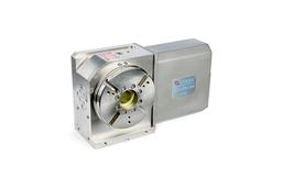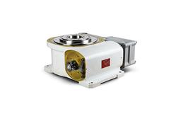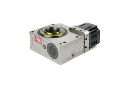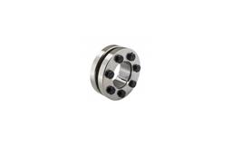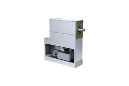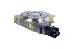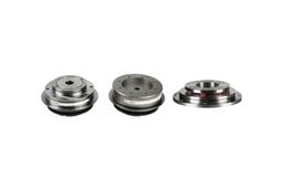
Index drive manufacturer, Shaft, Flange, Table type
Overview & Features
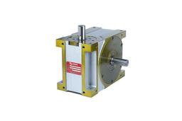
OSU/OSN (Oscillating Special Unit) is a device for automatic supply of work by using rotating roller gear cam, and up-down home cam and the model is used for high-speed and precise positioning.
OSU’s operating sequence is as follows. OSU descends and ascends 20~50mm to supply work, wheel 45°~ 180°, descend again to supply work, and ascend to return to its original position.
OSN’s operating sequence is as follows. OSN descends and ascends 20~80mm to supply work, wheel 30°~ 90°, descend again to supply work, and ascend to return to its original position.
Also, the model allows broad degree of freedom for timing chart and allows extensive response to a big turn angle.
Basic Structure
A complex device composed of 3 elements including two cams (roller gear cam & home cam) and cam follower.
High Speed
Refined cam curve, precisely processed cam, cam follower, and completely removed backlash allows high-speed operation.
High Productivity and Fixing
Quick setting time and precise positioning.
Less velocity fluctuation during operation and response to precise synchronization.
Economic Feasibility
No need for frequent maintenance and has excellent productivity for reducing the life cycle expense in automated system.
Product Code

| Number | Classification | Symbol | Explanation |
| a | Model | CF4 | Roller gear index drive |
| b | Size | 80 | Size of index driver. Indicates center distance of 80mm between input and output |
| c | Type | OSU | Indicates type of index drive.
|
| d | Serial Number | 2015 | OSU’s production serial number |
| e | CAM Curve | 2 | 1 : Modified Trapezoid Curve (MT) 2 : Modified Sine Curve (MS) 3 : Modified Constant Velocity Curve (MVC) 4 : Other curves |
| f | Input/Output Rotation Direction | R | Designates output shaft’s rotation direction to input shaft’s rotation direction
|
| g | Input Axis Specification | RW | Indication of direction on the input shaft and position of the moderator
|
| h | Input Shaft Specification | 5 | Indicates input shaft’s direction and reducer’s welding position |
| i | Welding Position | 1 | Designates welding position and oil gauge position
|
| j | Welding Hole in Machined Surface | VW | Designates welding hole in machined surface for welding index drive (refer to drawing) Welding hole is processed on two sides of VW in standard specification Fill in additionally when an welding hole is needed on R, S, T, or U side. Front processing is A. |
| k | Custom-Order | X | Fill in X for a special order other than special specification and standard ※ Attach items on special specification separately. ※ Indicate water-intake tolerance change, customer-order cam curve and angle, custom-order division, oil level, drain change, or designation. |
